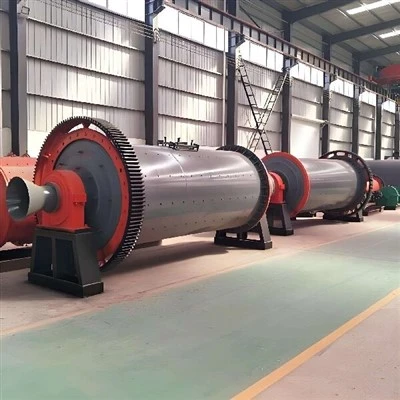
A ball mill is used to grind material into fine powder. A horizontal steel cylinder is partly filled with grinding balls. As the cylinder turns, the balls are lifted and then fall onto the material. Grinding is carried out by impact and attrition.
Ball mills are used in cement plants, mines and other industries. Material can be ground wet or dry. An open or closed circuit can be used. The mill and its grinding system are selected to suit the material and the required product.
Each part has a clear job. The shell holds the grinding charge. The supports carry the rotating mill. The drive turns it. This guide explains these parts and the checks needed to keep them in good condition.


How a Ball Mill Works

Two-compartment cement ball mill in a closed grinding circuit. Coarse material is returned by the separator.
The balls are lifted and dropped
The shell is turned by the drive. The balls are lifted along the inner wall by the rotating shell and liners. They then roll and fall onto the feed. Large particles are broken by impact. Finer particles are ground by rubbing between the balls and the material.
Material passes through the grinding chambers
Material is fed into the mill at the feed end. In a two-compartment cement mill, larger balls are used in the first chamber. The feed is broken into smaller pieces. Material then passes through the intermediate diaphragm. Smaller balls are used in the second chamber for fine grinding.
The product is discharged and separated
Ground material leaves the mill at the discharge end. In a closed circuit, it is sent to a separator. Fine product leaves the circuit. Coarse particles are returned to the mill for further grinding. This return flow is outside the mill.
Mill speed affects ball movement. If the speed is too high, the balls can be held against the shell instead of falling. This condition is reached at the critical speed. The working speed is kept below this level and is selected for the mill and its grinding duty.
Ball Mill Parts and Their Functions

Cutaway animation showing the rotating mill and grinding balls.
Shell
The ball mill shell is the outer cylinder. The grinding balls and material are held inside it. The shell is usually made from rolled steel plate. It must carry the grinding charge and transmit the drive torque.
Liners are fitted inside the shell to protect it from wear. Inspection openings are provided for maintenance. Shell joints, liner bolts and the areas around the openings should be checked during a shutdown.
End Covers
A ball mill end cover closes each end of the cylinder. It is also called a mill head. In a trunnion-supported mill, the load is passed from the shell through the head and trunnion to the main bearing.
The cover must be strong and well sealed. Its joints and fasteners should be checked. Poor sealing can cause dust leakage or material spillage. The feed or discharge arrangement is also connected at this end of the mill.
Trunnions
The ball mill trunnion is a hollow journal at the mill end. In a trunnion-supported design, the rotating assembly is carried by the trunnions and main bearings. Material is fed or discharged through the hollow opening.
The bearing surface must be accurately machined. Its condition should be checked for wear and scoring. The seals and connection to the head also need inspection. A slide-shoe-supported mill has a different support arrangement.

Shell

End Covers

Trunnions
Bearing Housings
The ball mill bearing housing holds the bearing in position. The bearing assembly is protected from dust and dirt. Lubrication connections and seals are fitted according to the bearing design.
The housing is not the bearing surface. Its mounting bolts, seals and lubrication connections should be checked. Leakage or loose fixings should be investigated.
Main Bearings
The ball mill bearing carries the rotating load and allows the mill to turn. High loads must be supported at low speed. The bearing type is selected to suit the mill design.
Correct lubrication is essential. Lubricant condition, supply and bearing temperature should be checked. Changes in vibration or noise should also be recorded. The photograph shows a rolling bearing example; other bearing arrangements are used on some mills.


Liner Plates
A ball mill liner plate protects the shell from wear. The liner profile also controls how the balls are lifted. Different profiles are used for different grinding duties.
As the lifting profile wears, ball movement can change. Worn or broken liners should be replaced according to the inspection results and maintenance plan. The fixing bolts and nearby shell areas should be checked at the same time.
Diaphragms
A ball mill diaphragm separates the grinding chambers in a multi-compartment mill. Material and ventilation air are allowed to pass through its openings. The grinding media are kept in their intended chambers.
The slots and plates should be checked for blockage, wear and damage. Restricted flow can affect grinding in both chambers. Damaged openings can allow media to pass between chambers. The diaphragm is separate from the external separator.
Pinion and Girth Gear
The ball mill pinion is the smaller gear in a girth-gear drive. It meshes with the large gear fitted around the mill. Power is passed through the drive to turn the shell.
The gears must be correctly aligned and lubricated. Poor contact can cause noise, vibration and tooth wear. Both the pinion and its mating gear should be inspected. The photograph shows the pinion, not the complete gear pair.
Grinding Balls
The grinding balls for a ball mill are the grinding media. The material is broken and ground by repeated contact with the balls. Ball size, material and charge level all affect the grinding work.
In a two-compartment cement mill, larger balls are generally used for coarse grinding. Smaller balls are used for fine grinding. Cast high-chromium media and forged steel balls are common choices. The media should be selected for the actual duty. Wear and broken balls should be checked regularly.


Where Ball Mills Are Used

Grinding in Cement Plants and Other Industries
Ball mills are used in several industries. The main duties are shown below. The mill design and operating conditions are different for each material.
In cement plants, raw materials are ground before kiln processing. Clinker is ground with gypsum and other cement constituents after the kiln. In mineral processing, ore is ground before separation. Coal grinding requires its own drying, ventilation and fire-protection arrangements.
| Industry | Main use | Material examples |
|---|---|---|
| Cement | Raw material and clinker grinding | Limestone, clay, clinker, slag |
| Mining | Ore grinding before separation | Iron ore, copper ore, gold ore |
| Power generation | Coal powder preparation | Coal |
| Chemical processing | Raw material grinding | Catalyst materials, zinc oxide |
| Ceramics | Body and glaze preparation | Quartz, feldspar, clay |
Four Checks for Reliable Operation
Check lubrication. The lubrication system should be checked each day according to the operating instructions. The main bearings and drive gears need the specified lubricant and supply. Low supply or dirty lubricant can cause serious damage.
Inspect liners and grinding balls. Liners and media should be checked regularly. Worn lifting profiles can reduce grinding performance. Broken balls may obstruct the diaphragm or discharge openings. Wear parts should be replaced before further damage is caused.
Watch vibration and noise. Changes in vibration and noise should be recorded. Loose foundation bolts, bearing wear or poor gear alignment may be involved. The cause should be checked early. Readings are best compared under similar operating conditions.
Control feed size. Feed size should be kept within the mill's operating requirements. Oversized pieces can cause heavy impact and liner damage. Where needed, the feed is reduced by a crusher before it enters the mill.
Before the mill is opened or entered, the site's isolation, stored-energy and confined-space procedures must be followed.
How to Prepare Replacement Parts
Replacement parts should be identified before they are needed. Drawings, dimensions, material requirements and fixing details should be kept with each part. Photographs are useful for identification, but the fit cannot be checked from a photograph alone.
The manufacturing route depends on the part. The illustration below shows a cast mill-head route. Mould preparation, pouring, heat treatment, machining and inspection are included. A fabricated shell, a forged pinion and grinding balls are made by different routes.

Cast mill head manufacturing: mould preparation, pouring, heat treatment, machining, inspection and packing.
Wear items and large critical parts should be planned separately. Inspection records should be used to plan liner, diaphragm and media replacement. Supply time should also be considered for heads, trunnions and drive parts.
Keep the Mill and Its Parts in Good Condition
The shell, end covers, trunnions, bearings, liners, diaphragms, pinion and grinding balls work together. Each part has a clear function. A fault in one area can affect the whole grinding process.
For operators and maintenance teams, these functions should be understood before an inspection is planned. Wear should be recorded, lubrication should be checked and replacement parts should be identified correctly. This helps keep the mill in service and reduces avoidable stoppages.